The best ideas come to me at 3AM when I'm trying to fall asleep.
In EDD our project involved using an ESP8266 WiFi module to communicate with a server. I realized how amazing this $3 module was that I bought a few for myself to play with. I was trying to think of cool projects to build with it when I found this:
This person basically used the ESP8266 to act like a chatbot and display a message.
Recently in our school we sort of adopted the S A D B O Y vaporwave culture ironically. We bought bucket-hats and started spelling English words out in Japanese.
I observed that a key component of vaporwave culture is outdated technology and a hopeless nostalgia to return to the 80s-90s era.
At 3 that night I had an idea to turn a TV into a text display.
Imagine you're in a basement
and theres an old TV sitting there. No cable box, no antenna. Just plugged into the wall.
Suddenly out of nowhere a message appears on the screen. White text on black. It's speaking to YOU.
I think I'm gonna install a camera somewhere and observe the victim, while I type in something creepy and strangely specific based on visual input from the camera like "I like your red shirt".
The television will be receiving input from an Arduino connected to a chat box through the ESP8266.
I think it'll be a lot of fun to build.
I haven't completed it yet, but so far I am able to type text to the serial port and have it displayed on the TV.
I will walk you through the process of the build so far.
Take apart the TV. It should be unplugged of course. Use a screwdriver to short some capacitors if you're paranoid. CRT monitors use a flyback transformer which can do some serious damage to you.
I would recommend vacuuming out spider webs and dust before continuing. It would make the build a lot cleaner, and safer.
You should where the audio and RCA plugs are located on the TV. This is a pic of the circuitboard.
Solder 3 wires: GND, Audio, Video
This is just a fun artsy pic of the electronics inside of a television.
You can get a USB wall charger at Five Below for... $5.
You will need this so that you can power your Arduino inside of your TV without another cord. The idea is so that there is only one cord from the TV: power. The Arduino and all the circuitry will be inside the TV once it's done. The idea is stealth so that the TV looks like it has a soul of its own.
Cut the plug off.
Strip the wire. Cheap chargers like this only have + and - wires
Find where the wall plug power goes into on the TV.
Get two >=18 gauge wires
Solder them onto where the wall power comes it
Solder the other end to the phone charger. The charger is now in parallel to the TV whenever the TV turns on.
You will really want to wrap this well in electrical tape: maybe you even want to seal this off with glue.
When the TV is plugged in, you should get ~5v from the charger.
According to the TVout library, you will need two resistors for the circuit
Make sure you install the TVout library for Arduino.
Wire up the circuit
Upload the TVout example and turn on the TV.
It works!
I wrote my own code which I will publish later that writes to the TV whatever is inputted on the serial monitor. We needed to set a baudrate of 1200 because the TV is very slow.
The future goal is to implement this tiny $3 WiFi module.
You want to work on a surface that will not be damaged by heat. In this case I worked on some ceramic tiles and newspaper.
This was the outcome of the first bend (crack is from the failure last time).
Turn on the heat gun to full heat and run it up and down the line until the acrylics gets all floppy.
When it's malleable enough, you can bend it to the correct angle and hold until it sets.
Doing the second bend
All the bends are complete! we have a nice triangle.
I bought a huge sheet of faux leather for $10. I will be covering the frame in this so it looks sweg.
Mark out the surface area of the triangle. Leave extra room for folding.
This part isn't totally necessary, but it's good practice. You will want to line the inside of your speaker enclosure with some sort of dampening material so it doesn't vibrate and sound crappy.
I used some material from an air filter. Here I measured out how much I needed.
Cut holes for the speakers.
I secured the material in place with hot glue.
I didn't have a great method of securing the leather onto the surface. I used a combination of glue stick glue and hot glue to secure the leather in place.
Simply wrap the leather around the plastic casing.
The downside of using some sort of solid glue is that it leaves marks.
After you're done wrapping, cut out the holes that were there with a knife.
This next part is an overview of the circuitry inside of the portable speakers.
I took apart a portable phone charger for the 5v power source. This power source was a bit small and couldn't provide sufficient power for max volume. You would want to take apart a battery back that has more than 1000mAh capacity.
I removed the USB socket from the board to save space.
Soldered wires to the aux female connector.
Soldering the aux plug to the PAM8403 amplifier.
Here, everything is connected.
Speakers connected to respective "left" and "right" outputs of the PAM8403 amplifier
TRS female connected to respective "left" and "right" inputs of the amplifier
Power source connected to switch, connected to the amplifier.
We almost forgot to add bluetooth!
I bought a USB powered bluetooth module for ~$5. These are extremely useful if you want to add bluetooth audio to your car.
We just need to take this apart, connect it to the speaker power, and connect the audio output in parallel to the existing plug.
I asked a friend to cut out the endcaps for this project. The outcome was beautiful.
After all the electronics were finished, I shoved everything into the speaker box and glued in the end caps.
I have the recharging circuit board poking out so I can charge it
Suggestions for the future:
Use a 10,000mAH power source. with more power, your speakers will be louder, last longer, and have exceptional range for bluetooth
perhaps have a circuit board in the future so the inside isn't a messy nest of wires.
I made this project a year ago last summer. I was bored at home and I didn't want to do my summer homework.
http://www.instructables.com/id/Krugers-Zippo-Remote/
I started this draft also a year ago but I never got around to finishing it.
First a video:
I made this, again, when I was bored. The only thing I enjoyed about this was trying to sync up the music to the actions but this is actual trash.
If you go to 0:20 and 1:51 of the video, you'll see this guy pressing a button on a Zippo lighter and then an explosion ensuing that action.
It's safe to assume that this awesome lighter wasn't for lighting up cigarettes but rather explosives
fun stuff.
Last year I was literally obsessed with these lighters. I still think they're awesome. I was really fascinated by the way the whole lighter was packaged. I thought to myself "what else can I fit in this thing..."
Watching Captain America gave me some ideas.
Please excuse the title and the music. I was in a pretty good mood that day and I thought it was an excellent idea.
The video only shows ONE way you can use the Zippo remote. You don't only have to use it for filling your basement with smoke. You can use it to open garages, turn on your ceiling fan, start your oven, whatever. You can do anything electrical with it.
The real instructions are in that Instructables link up top, but I'll do some brief documentation on it below.
First get a lighter. get an ATtiny45 or 85 with a V suffix. thats right.
ATTINYX5V- 10PU is the part you want. This means it runs on low power very efficiently and we need that.
I'm not going to go into too much detail about the parts.
Just a picture comparing two lighters. The one on the left is fake which is why I don't mind taking it apart.
Some pictures of what the Zippo insert looks like. This one is fake.
We will be replacing the flint with a button, and placing an LED right next to the wick.
Take out the flint thing.
remove the wick and all the cotton balls.
put that stuff in a safe place. Cut a little piece of wick that we will be using to cover up the LED.
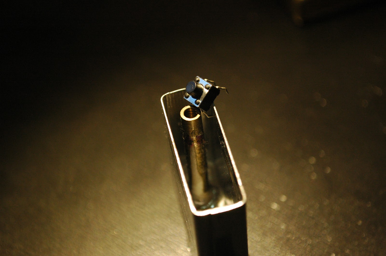
The idea is that we put a button on the bottom of the flint shaft. When we press down on the flint wheel, it pressed down on a shaft that presses on that button.
Where the purple marker is is where the LED will fit in.
secure your insert. We'll be torturing it and you don't want it to slip away.
What I did to make the LED hole was literally hammer a hole through the steel casing. I used a nail.
You can see a nice hole next to the original flint hole.
I then used a Dremel rotary tool to slowly and carefully cut away and sand down the flint tube.
When its finished the flint tube should be shorter, and the button should fit in the tube snugly.
Finished view.
This part is pretty annoying. I was planning on using the Zippo case itself as the antenna of the remote. In order to do that I need to solder the antenna to the insert. I can't solder to steel.
The only solution was to electroplate a portion of the insert in copper so i could a wire to the case.
The solution is copper sulfate. On the cathode I'm using a 1970s penny and the anode is going to be the lighter.
Just run 12v through it and electroplate until you got something.
So after plating I did get some copper to stick on! Nice.
shove in that short piece of wick we cut earlier
Glue down the bottom of it with epoxy so it can't get pulled out.
Some pictures of a button.
The idea is that the button part of the button fits INSIDE the tube while the rest of the button housing rests on the edges of the metal flint tube.
A piece of tough wire acts as a shaft to translate the force from the flint wheel push down do the button.
Get some scrap plastic. Don't ask we're going to do something silly.
Cut the plastic down to shape so it fits like so.
You will need to enlarge the first portion of the tube a bit with a drill so the button part can fit in.
Put in the flint, the wire shaft, the button, then glue the button to that plastic piece.
The plastic piece will be glued to the insert wall.
The flint should be firm. When you press down on the flint wheel, you should feel a click.
This process was really hard, and it wasn't even the most difficult part. It took me about three days to get it right, so be patient.
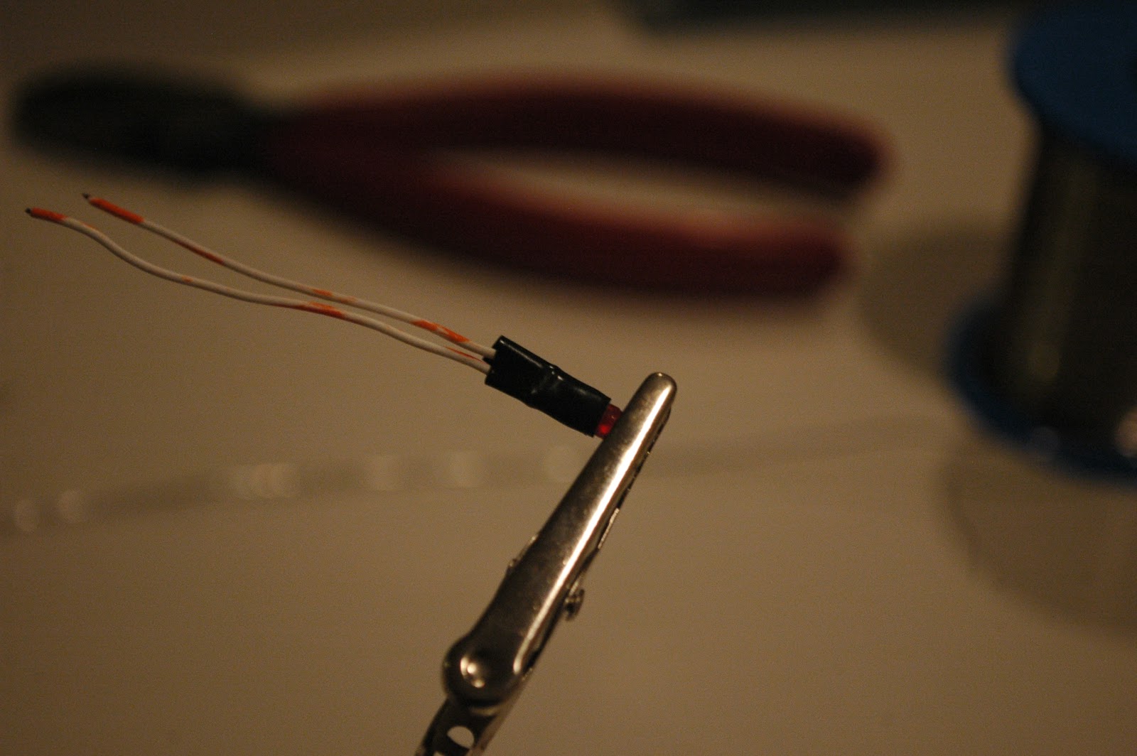
3mm LED!
Solder wires
Electrical tape
Heat shrink it. We don't want things shorting out on the metal Zippo insert.
Shove the LED into that hole we made earlier with the nail. Glue it in place.
The hardest of hardware has been finished. Now comes the less hard but more involved part: writing the code, designing the circuit, etc.
Here are the 433MHz modules I'm using. I know they vary in size and stuff, but you want to use this specific one. It's the perfect size to fit inside a Zippo insert.
Cut out your PCB and print out your design.
The PCB I'm making right now is the receiver module for the remote. You don't have to make this.
Wait 7 minutes for exposure.
Develope it.
cover edges in nail-polish if you like.
etch it. We'll get back to this.
We want to use this rechargeable battery. Its 3.7V LiPo. I forgot the specific size and specs but if you're interested in more than just looking at pictures, it's all the Instructable.
Wrap it in black electrical tape so it doesn't short stuff out.
>So in this picture I soldered a 16MHz crystal to the ATTINY45 chip. Don't do this. We don't need this. Just ignore the crystal.
Solder a resistor
If you notice, I'm trying to make the circuit compact as possible. This involves ripping off unneeded pins.
Or desoldering them...
Solder the battery to the necessary places.
I wrapped the transmitter in tape so nothing shorts out, and used magnet wire so it's thin.
More complicated soldering.
Resistor soldered to the LED wire.
Connecting the device to the LED.
Solder the connections to the button.
Your circuit is about done. Make sure your battery JST connector is accessible when you need to charge it. It's been a year since I built it and I have YET to need to recharge the battery.
BACK TO ETCHING.
Etched PCB.
Soldered parts (details in instructables)
Basically this receiver turns on a relay for 5 seconds when it receives the signal from the Zippo remote control.
V = flambda to calculate antenna length.
The blue connecter is so you can switch anything you want.
Green means ready. Red means ACTIVATED.
It's powered by 3 AAA batteries.
There's a lot of bare metal parts exposed that run a high risk of shorting out.
The solution is to cover anything exposed with nail-polish. This works like a charm.
Applying a second coat will ensure that nothing goes wrong.
Gently shove all the electronics into the Zippo case.
Everything barely fits. The JST connector is exposed so I can easily recharge.
Reinsert the insert and you're done!
You can recharge by using USB power and possibly blowing up your circuit. I recommend readers to invest in a safer way of charging LiPo batteries, unlike what I'm doing in this picture.
So now you have a remote control in a Zippo lighter. Be safe and don't do silly things with it. I'm not responsible for what you do with it. Please have fun, but don't hurt yourself and others.