Showing posts with label SMT. Show all posts

Sunday, December 22, 2013

Aluminum PCB Attempt (1)

Making PCBs at home is awesome.
Feel the power of making a professional-looking circuit board at home with these amazing chemicals that eat copper.

Pretty rad.
Sadly, not everyone can get their hands on etchant, or photosensitive boards, or any of that fancy stuff. As always, I investigated a cheaper way to make PCBs. I'm not talking about that 3D printing stuff or the conductive ink pens (those things are not cheap to begin with).

I'm talking real lyfe.

Okay. So the objective of this was to make a PCB that could use any substrate. That means I could implement a circuit on any surface: wood, glass, plastic, curved surfaces, paper, maybe even clothing!
Before we continue on how I did this, we must first understand how PCBs work.

Basically, a sheet of copper is pasted on top of an insulative substrate: usually phenolic or fiberglass, or flexible plastic. Printed Circuit Boards are much more sophisticated today, with multiple layers. These layers are connected through vias. Like elevators, they are conductive holes that transport electrons.

Here are some pictures from the internet:
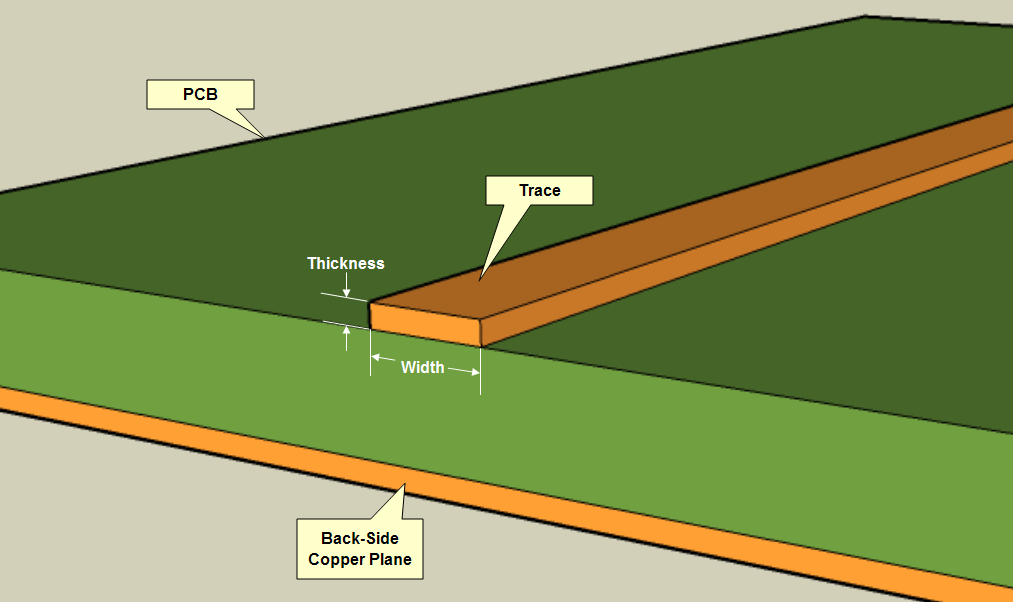
As you can see, each trace is like a wire, a road to move electrons.

PCBs can get crazy, with layers of different types of conductors. A solder mask is that green thing that prevents the PCB from oxidation or shorts.
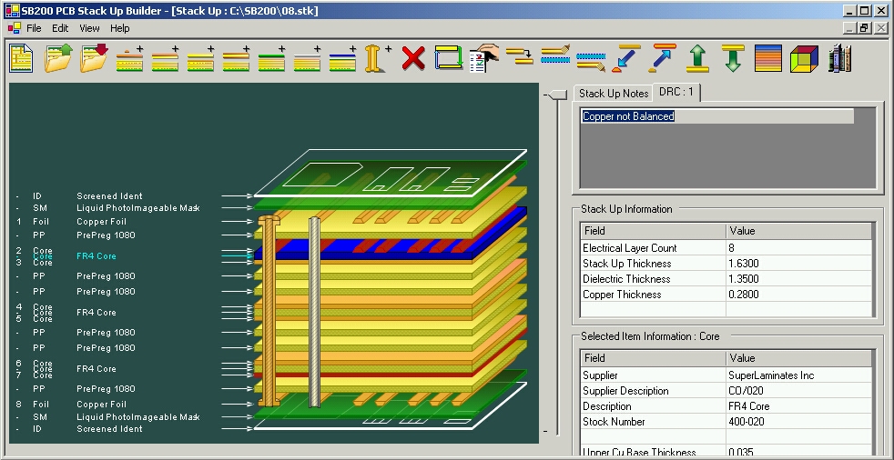

More.


Now that you get the point of how these PCBs work, people usually make PCBs at home by etching away copper from a copper-clad board to get traces.
You could look at my post on VU meters evolution to get an idea of how I do it at home.


So, it seems like PCB manufacturing at home is limited to copper boards on phenolic/fiberglass surfaces.
Instead of using copper sheets (because they were not cheap), I used aluminum foil as the conductor. Instead of using fiberglass/phenolic, I used whatever I felt like. The following is my attempt on aluminum PCBs.


I decided for attempt 1 that I was going to use a plastic sheet


For this first attempt I was going to use SMD parts, so I do not have to drill holes (the DIP parts will be bent into SMD).


Sanded out


Just programming the chip


I really had no photosensitive aluminum foil, so I would use the toner transfer method.


I cut out one piece.


Taped it to aluminum foil. The back of the foil has a piece of tape to keep it flat.


Then I ironed it. The tape melted, which was bad...


The toner stayed intact with the foil, but the end product wasn't flat.


Use crazy-glue to glue it onto the plastic


Bath in water to remove the paper


It did not glue on too well... there were air gaps and wrinkles


dangerous chemicals.


crack a window.


two parts hydrogen peroxide


one part hydrochloric acid


It should etch the aluminum pretty well.


You will start to notice that the etchant gets in the cracks...


It etched away at traces from below.


So this time, I would glue the aluminum onto a flat surface first.


Then I drew silly patterns on it with a circuit-writer pen (an oil based ink pen, it's a Sharpie in essence).


I put it in.


Working well!


Then the ink started dissolving...


It didn't come out too well...


Conclusion from attempt 1:
You must always put the substrate on the foil first to ensure an airtight bond that will not allow any etchant in between.
This means that you cannot use a substrate that melts under a clothing iron, because...

Conclusion from attempt 2:
Oil based ink does not last too well in our etchant.

This PCB attempt could have been successful, if I were using glass, for example.

However, I was not using glass. In the end, this was pretty much a failure. The goal was to use any substrate. I am currently limited to substrates that do not melt under a clothing iron.

This gives me a nugget of information for my next attempt though, which is good, so I got that going for me.


Saturday, August 31, 2013

DIY Arduino Mega 2560

Alright.
Here's the story: I was working on this frustrating Arduino project, and I decided to take a break. I went away to watch a little Star Trek and drink some water.
When I came back, my Arduino Mega was hot: really hot.
In this area:
The Arduino was not responding to the IDE. The only way I could program it was by using the USBtiny ISP.
That pretty much ruins the purpose of an arduino board, so I brought out the solder pot, desoldered the whole board, salvaging as many parts as I could.
Since the ATmega 2560 was not damaged, I decided to put it back to use:
The following is the process of how to

Make your own Arduino Mega

You think it's hard to solder SMD? Think again. This was my first time soldering SMD chips with 0.5mm pitch (in other words, REALLY SMALL).

Parts needed:

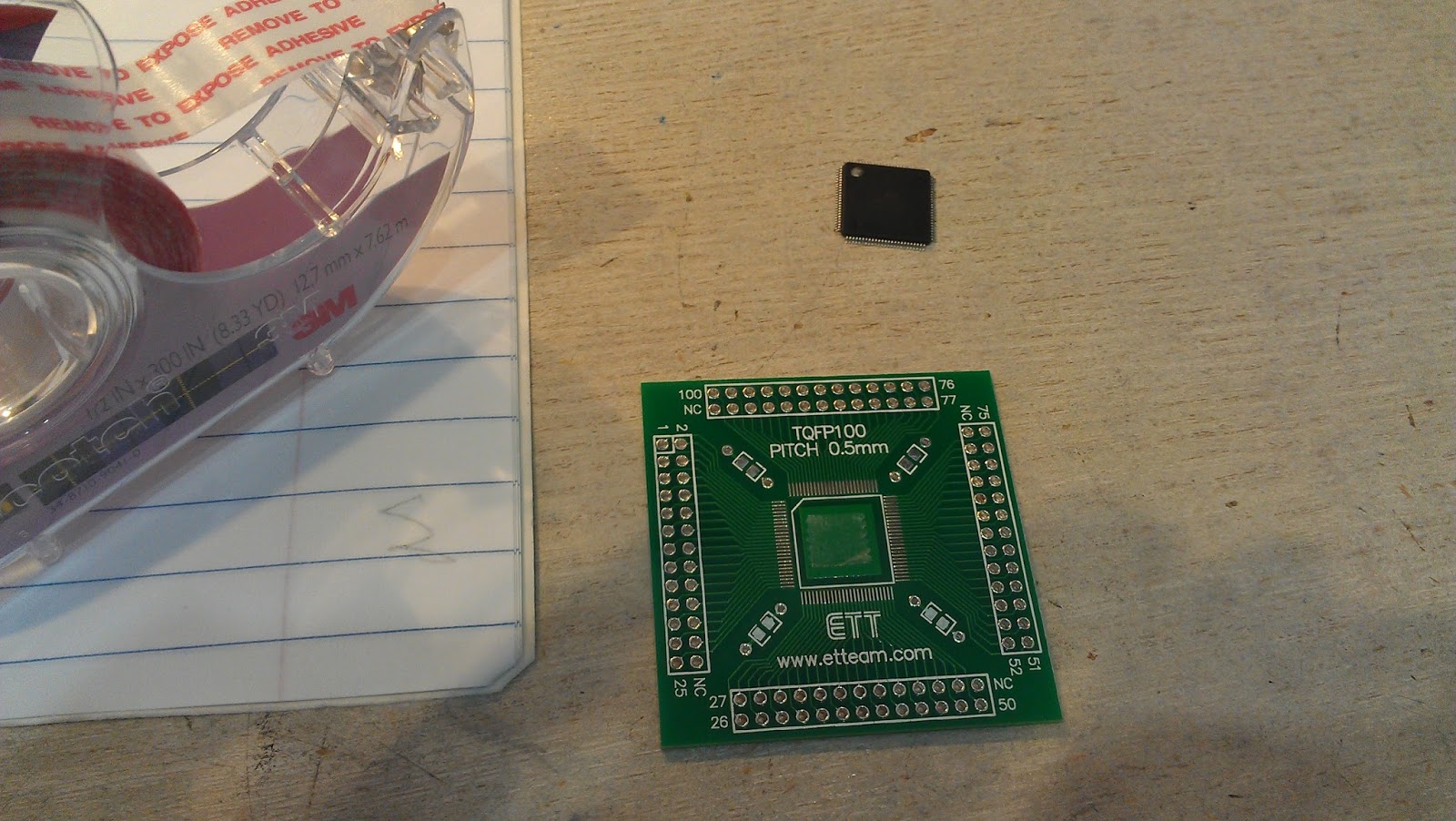
  • TQFP100, 0.5mm pitch to DIP adapter
  • Momentary push button
  • 6 headers (for ISP)
  • lots of wires
  • flux
  • Perf board
  • 16 MHZ crystal (if you salvaged chip from Arduino Mega)
  • OPTIONAL but recommended - double sided tape
  • OPTIONAL - 330 - 470 ohm resistors *2
  • OPTIONAL - two LEDS
  • OPTIONAL - 5 more headers for FTDI Serial communication
  • OPTIONAL - nuts and bolts

Step One

Stick one or two pieces of square double sided tape on the breakout board. This might help keep the chip in place when soldering it.

Step Two

Place the chip on! Please note the index corner on the chip to align it correctly. Make sure that the leads on the chip and the board line up REALLY well. The must be aligned.


Step Three

Time to start the soldering: apply WAY TOO MUCH flux (that means A LOT) onto the edges of the chip. You will need to use all of it, and maybe some more.
The secure the board:

Step Four

I do not have pictures for this. You will want to put a nice drop of solder on your iron and just drag it across the edges of the chip. Don't worry, it's all being soldered, even if you do not think it is.
You will probably have many solder bridges (especially on a chip this small).
Thats OK, just gently drag it off with the iron tip, use a solder sucker (be careful with it, you might bend the leads), or use even more flux to remove it. This step might be the most difficult

Step Five

Clean off the flux with water or alcohol:

Test the connections: any shorts? Something not connected?
Then you may proceed to cut and solder in some headers.


Then maybe you want to drill some holes in the four corners, if you want to.

Step Six

This step is mildly annoying. Print out the datasheet of the 2560 and start marking where
MOSI
MISO
SCK
TXD0
RXD0
pin#27
VCC
GND

or any pins important to you, are
Mark it all!

This might help:


Step Seven

Start preparing your perf board. This step is very subjective to your needs and tastes. I like to have the TX and RX header so I can program this like a regular arduino.
I like to have a reset button
I like to have an LED on pin D13/ 27 of the chip
After all, it is a development board.


Start wiring the board!


Do some three dimensional wiring now.


Step Eight: last step

Time to test it....

The ISP programming worked!

Serial communication works.


 FINISHED:


Static......

Alright. It worked. Beautifully.
But I have something to admit. As I am typing this post, The finished board is hung up on my wall as a failure.

Why?

I can't use it as a regular Arduino Mega as I wished. Well, maybe I could have, but you will see why I couldn't.
The old Arduino Mega uses the FTDI UART, however the chip was the ATmega1280
I have a 2560, so I would need to go into some hassle to add a new board bootloader into Arduino IDE and all that trouble is just not worth it.

It definitely can be accomplished, however before I could do anything, the board burnt out.
*sigh*
I was in the middle of testing the serial communication: it worked perfectly. After five minutes, however, it started glitching. Then there were sparks... then smoke, then everything went south.
What happened?

/********************************************************************************/
READ THIS
When soldering in the oscillator crystal, make sure it DOES NOT SHORT THE LEADS. Note that it has a metal casing, so it should either be masked with electrical tape or place in another area.
Don't do this:
That ended up shorting XTAL 1 and 2, Vcc, and GND all together. The chip smoked and I wasted a lot of effort.

Lesson learned! *thats another nugget of information buddum crash*

As long as you follow all of these instructions, however, you will be able to accomplish what I would have if I have not made that mistake!