Sunday, October 11, 2015

I bought a watch

So this is going to be one of those not-so-technical posts.
I bought a watch this week at Sears.

I love this picture.

The gold watch on the far left is the one I've been wearing for a while. I practically built the thing.
I bought a fake Casio A159W watch, then bought a Casio F-91W and replaced the fake A159W with the innards from the F-91W.
So that way I have a gold watch that won't break if I submerse it in water or drop it on the ground.
I bought the oyster watch band to fit onto the watch. It's a pretty much a unique watch because I custom built it.

The silver watch on the top is a classic Casio A168W. Nothing too special about it.

The watch that I bought this week is the two tone analog watch to the left. That's what I bought for 60% off of $35, so I bought it for $15.

Chain shows up in everything.


I didn't realize this when I bought it, but the Decade brand watch looks extremely similar to...
a Rolex Datejust
http://www.rolex.com/watches/datejust/m116233-0149.html

a $12,000 watch. I was thrilled to realize this because I love buying knockoffs. It's flashy in a sort of ironic way.
Here are some main similarities:
  • Fluted bezel (that gold ring around the whole watchface)
  • twotone 
  • Jubilee bracelet
  • Gold crown (that thing to adjust the time)
Some main differences
  • One is 1000x more expensive
  • Decade's bracelet is not solid metal
  • Decade's watch does not have date
  • Decade's watch is based on quartz movement, while Rolex is mechanical
  • Decade is just really cheap in all aspects. It's actually a terrible watch.
It's so cheap and that's why I love it. This Friday I didn't want to write college essays so I took some time to engrave my watch.
As seen on my Snapchat story:


I engraved my initials TSJW on the flip clip. I usually wear my watch on the inside of the wrist, and there's nothing to show off on the outside if I do this. So I felt like engraving my initials on the outside makes it feel less wrong wearing my watch on the inside.

It's so embarrassing to wear now.

So that's just some background on the watch. 
Whenever I buy something, I always end up thinking about taking it apart and modifying it (its inevitable).
A few days ago I got the watch wet and had to take it apart to dry out the moisture.
I realized how spacious the inside of the watch was... the quartz movement mechanism took up only an eight of the total space inside the watch... That gave me ideas.

The idea:

I honestly really don't like wearing analog watches. They give me a good sense of how much time is left in the day, but I spend at least five seconds reading it in order to understand what time it is actually. On a digital watch the numbers would just show up in X:XX form, but on this watch I have to spend a good amount of time decoding the placement of the hands.

Plus, the gold hands blend in with the gold face and everything is just so shiny and it makes it IMPOSSIBLE to read the time.

I love wearing digital watches, but they aren't flashy enough.
The Casio watch I have right now isn't solid metal: It's metal plated and then gold plated, which means that after wearing it for a year the gold wears off (it already has).

Literally no one sells a solid metal gold-plated digital watch at an affordable price.

So here's the idea: replace the quartz movement in the watch with a digital watch module.

Sorry, I don't have any picture of this right now (because taking apart watches is actually the worst), but imagine the Decade watch with a display like this:

Right now there are a few problems, and a few solutions that I've been thinking of.
  • Fitting the innards from another digital watch into the Decade watch
    • find a small enough watch, and 3D print a holder that will make it fit snuggly so it doesn't shift around.
  • What do you do about the four buttons on a digital watch when you only have a hole for one crown on an analog watch case?
    • I still need to figure this out.
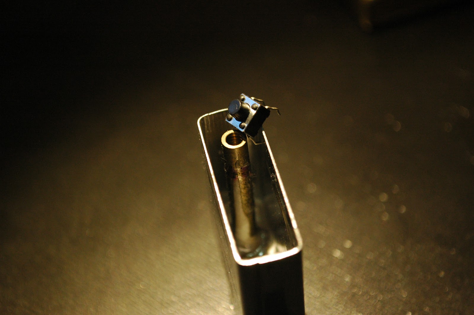
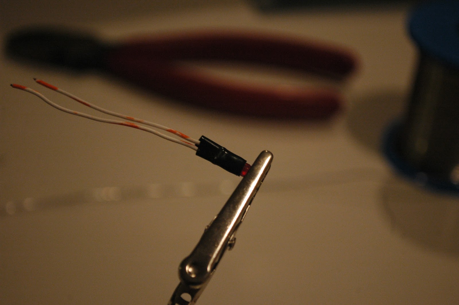
For now I need to put off this project to concentrate on college applications, but I think this is a worthwhile project to look into. It'll probably be more difficult than my Zippo remote project, because this time I'm dealing with something a little more expensive than a lighter.

Hopefully when I come back to this idea a few months later I would have made some progress.

Sunday, October 4, 2015

Badass Zippo Remote

I made this project a year ago last summer. I was bored at home and I didn't want to do my summer homework.
http://www.instructables.com/id/Krugers-Zippo-Remote/

I started this draft also a year ago but I never got around to finishing it.
First a video:

I made this, again, when I was bored. The only thing I enjoyed about this was trying to sync up the music to the actions but this is actual trash.
If you go to 0:20 and 1:51 of the video, you'll see this guy pressing a button on a Zippo lighter and then an explosion ensuing that action.

It's safe to assume that this awesome lighter wasn't for lighting up cigarettes but rather explosives

fun stuff.

Last year I was literally obsessed with these lighters. I still think they're awesome. I was really fascinated by the way the whole lighter was packaged. I thought to myself "what else can I fit in this thing..."
Watching Captain America gave me some ideas.


Please excuse the title and the music. I was in a pretty good mood that day and I thought it was an excellent idea.
The video only shows ONE way you can use the Zippo remote. You don't only have to use it for filling your basement with smoke. You can use it to open garages, turn on your ceiling fan, start your oven, whatever. You can do anything electrical with it.

The real instructions are in that Instructables link up top, but I'll do some brief documentation on it below.

First get a lighter. get an ATtiny45 or 85 with a V suffix. thats right.
ATTINYX5V- 10PU is the part you want. This means it runs on low power very efficiently and we need that.
I'm not going to go into too much detail about the parts.


Just a picture comparing two lighters. The one on the left is fake which is why I don't mind taking it apart.


Some pictures of what the Zippo insert looks like. This one is fake.


We will be replacing the flint with a button, and placing an LED right next to the wick.


Take out the flint thing.


remove the wick and all the cotton balls.


put that stuff in a safe place. Cut a little piece of wick that we will be using to cover up the LED.


The idea is that we put a button on the bottom of the flint shaft. When we press down on the flint wheel, it pressed down on a shaft that presses on that button.


Where the purple marker is is where the LED will fit in.


secure your insert. We'll be torturing it and you don't want it to slip away.


What I did to make the LED hole was literally hammer a hole through the steel casing. I used a nail.


You can see a nice hole next to the original flint hole.


I then used a Dremel rotary tool to slowly and carefully cut away and sand down the flint tube.


When its finished the flint tube should be shorter, and the button should fit in the tube snugly.


Finished view.


This part is pretty annoying. I was planning on using the Zippo case itself as the antenna of the remote. In order to do that I need to solder the antenna to the insert. I can't solder to steel.
The only solution was to electroplate a portion of the insert in copper so i could a wire to the case.


The solution is copper sulfate. On the cathode I'm using a 1970s penny and the anode is going to be the lighter.
Just run 12v through it and electroplate until you got something.
Here's a guide on electroplating:
http://www.instructables.com/id/High-Quality-Copper-Plating/


So after plating I did get some copper to stick on! Nice.


shove in that short piece of wick we cut earlier


Glue down the bottom of it with epoxy so it can't get pulled out.


Some pictures of a button.


The idea is that the button part of the button fits INSIDE the tube while the rest of the button housing rests on the edges of the metal flint tube. 


A piece of tough wire acts as a shaft to translate the force from the flint wheel push down do the button.


Get some scrap plastic. Don't ask we're going to do something silly.


Cut the plastic down to shape so it fits like so.


You will need to enlarge the first portion of the tube a bit with a drill so the button part can fit in.


Put in the flint, the wire shaft, the button, then glue the button to that plastic piece.


The plastic piece will be glued to the insert wall.


The flint should be firm. When you press down on the flint wheel, you should feel a click. 

This process was really hard, and it wasn't even the most difficult part. It took me about three days to get it right, so be patient.


3mm LED!


Solder wires


Electrical tape


Heat shrink it. We don't want things shorting out on the metal Zippo insert.


Shove the LED into that hole we made earlier with the nail. Glue it in place.

 The hardest of hardware  has been finished. Now comes the less hard but more involved part: writing the code, designing the circuit, etc.


Here are the 433MHz modules I'm using. I know they vary in size and stuff, but you want to use this specific one. It's the perfect size to fit inside a Zippo insert.


Cut out your PCB and print out your design.
The PCB I'm making right now is the receiver module for the remote. You don't have to make this.


Wait 7 minutes for exposure.


Develope it.


cover edges in nail-polish if you like.


etch it. We'll get back to this.


We want to use this rechargeable battery. Its 3.7V LiPo. I forgot the specific size and specs but if you're interested in more than just looking at pictures, it's all the Instructable.


Wrap it in black electrical tape so it doesn't short stuff out.


>So in this picture I soldered a 16MHz crystal to the ATTINY45 chip. Don't do this. We don't need this. Just ignore the crystal.


Solder a resistor


If you notice, I'm trying to make the circuit compact as possible. This involves ripping off unneeded pins. 


Or desoldering them...


Solder the battery to the necessary places.


I wrapped the transmitter in tape so nothing shorts out, and used magnet wire so it's thin.


More complicated soldering.


Resistor soldered to the LED wire.


Connecting the device to the LED.


Solder the connections to the button.


Your circuit is about done. Make sure your battery JST connector is accessible when you need to charge it. It's been a year since I built it and I have YET to need to recharge the battery.


BACK TO ETCHING.


Etched PCB.


Soldered parts (details in instructables)
Basically this receiver turns on a relay for 5 seconds when it receives the signal from the Zippo remote control.


V = flambda to calculate antenna length.


The blue connecter is so you can switch anything you want.


Green means ready. Red means ACTIVATED.
It's powered by 3 AAA batteries.


There's a lot of bare metal parts exposed that run a high risk of shorting out.


The solution is to cover anything exposed with nail-polish. This works like a charm.


Applying a second coat will ensure that nothing goes wrong.


Gently shove all the electronics into the Zippo case.


Everything barely fits. The JST connector is exposed so I can easily recharge.


Reinsert the insert and you're done!


You can recharge by using USB power and possibly blowing up your circuit. I recommend readers to invest in a safer way of charging LiPo batteries, unlike what I'm doing in this picture.


So now you have a remote control in a Zippo lighter. Be safe and don't do silly things with it. I'm not responsible for what you do with it. Please have fun, but don't hurt yourself and others.

Thanks for reading!