Showing posts with label Etchant. Show all posts

Friday, January 17, 2014

PCB Agitator

Hello Again!

Over the past years I have been making PCBs by just watching it etch away. Sometimes I would heat up the chemicals in the microwave, jiggle it around manually, use a stirrer, or a straw to facilitate the etching process. 
You all probably know that by agitating the etchant, it etches faster. I don't throw out etchant that often (in fact I have never), so my it gets old, colorful, and ineffective.

Since I do not want to manually agitate, I decided to have an automatic agitator. There are many designs out there already.

Here are some just to name a few:


I wanted to build one of these, but I did NOT want to use $30 hardware (Arduino) to do a simple back and forth motion, and I did NOT want to deal with the crazily pinned 4017 decade counter.

Seriously.
Look at the pinout of LM4017. It's crazy and not easy to play with.
Can't you just put Q0-Q7 in order?

So, I really simplified the design.

First of all, I would not have done this without the guys on the Arduino Forum.
I would like to give a special thanks to michiyon, TomGeorge, JohnLincoln, MarkT, MAS3, polymorph, and cjdelphi

My circuit was originally not functional, but I got help. Click the link if you want to see the debug process.

So, here is the schematic.

There are many things you can do to change this for it to work better, for example,
  • connecting pin 4 on 555 to 9v
  • connecting pin 5 to 0.1 uf capacitor to ground
  • connecting the relay coils in series than in parallel
  • probably many other things I am forgetting
The reason I did not add these were for simplicity. This is the bare circuit.

You need:
  • 100 uf capacitor
  • 2*1k resistor
  • 10k resistor
  • 2*5v relay
  • 9v battery and clip
  • 2n2222 transistor or the like
  • CD drive
  • 4007 power diode (or the like)

Here is how I assembled it:


Two relays taped together. The two SPDT relays with the same coil connect make a DPDT relay to function as an H-bridge.


Tight soldering!


The 555 timer


Taken apart CD drive.


The motor for the eject.
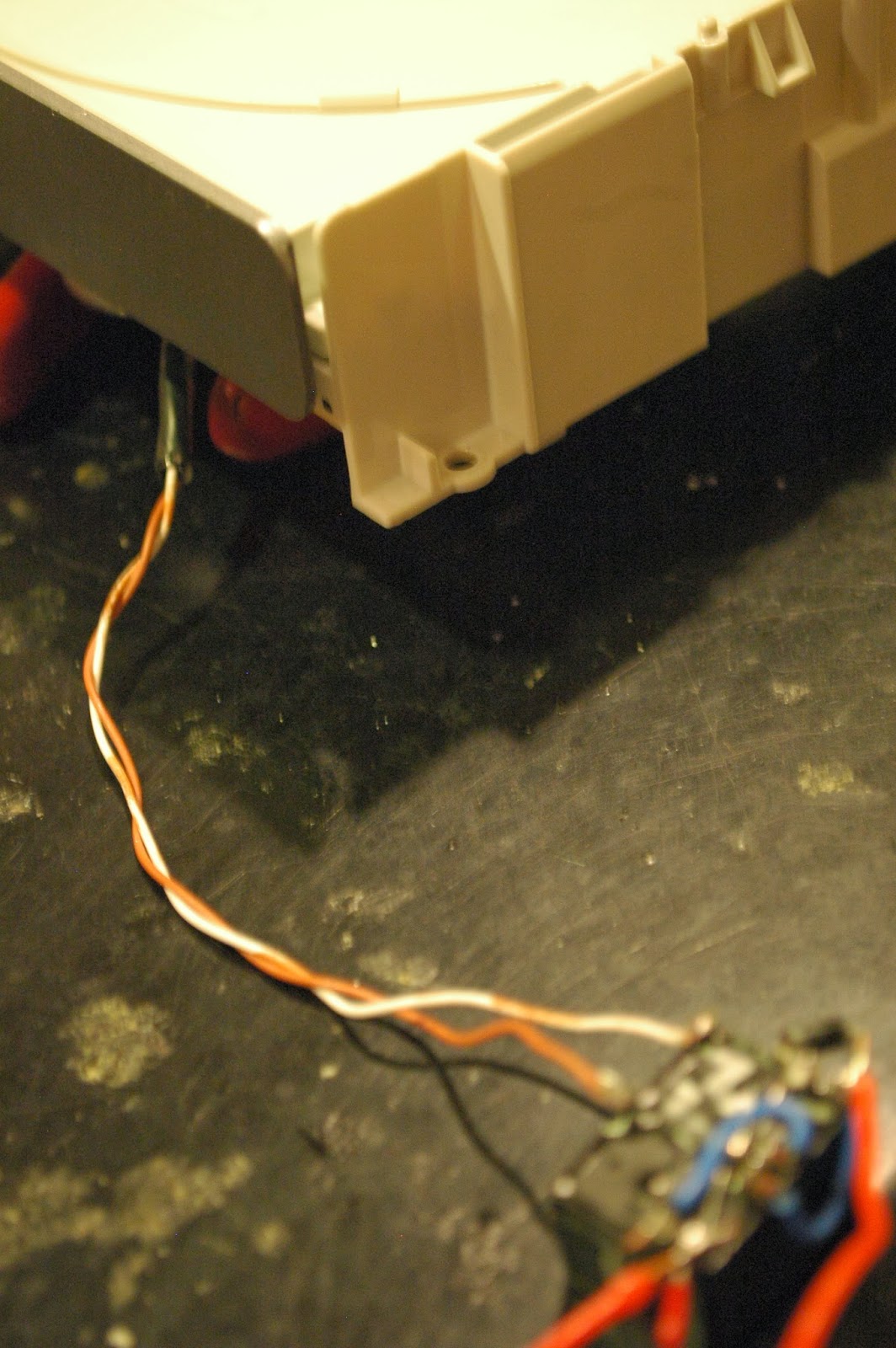

 If you can follow the schematic you are golden. Make a PCB, use a perfboard, whatever; I just made a rat's nest to keep it small.

Here is a video:


It is a bit kicky, probably because of a current issue, but it works for now.
And it's a lot cheaper than the other PCB agitators, using less parts :D

I hope you enjoy it.

Sunday, December 22, 2013

Aluminum PCB Attempt (1)

Making PCBs at home is awesome.
Feel the power of making a professional-looking circuit board at home with these amazing chemicals that eat copper.

Pretty rad.
Sadly, not everyone can get their hands on etchant, or photosensitive boards, or any of that fancy stuff. As always, I investigated a cheaper way to make PCBs. I'm not talking about that 3D printing stuff or the conductive ink pens (those things are not cheap to begin with).

I'm talking real lyfe.

Okay. So the objective of this was to make a PCB that could use any substrate. That means I could implement a circuit on any surface: wood, glass, plastic, curved surfaces, paper, maybe even clothing!
Before we continue on how I did this, we must first understand how PCBs work.

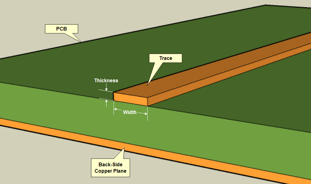
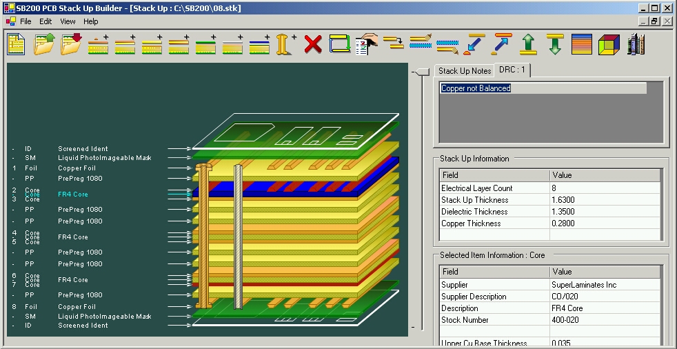
Basically, a sheet of copper is pasted on top of an insulative substrate: usually phenolic or fiberglass, or flexible plastic. Printed Circuit Boards are much more sophisticated today, with multiple layers. These layers are connected through vias. Like elevators, they are conductive holes that transport electrons.

Here are some pictures from the internet:

As you can see, each trace is like a wire, a road to move electrons.

PCBs can get crazy, with layers of different types of conductors. A solder mask is that green thing that prevents the PCB from oxidation or shorts.


More.


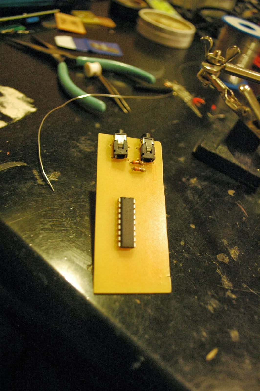
Now that you get the point of how these PCBs work, people usually make PCBs at home by etching away copper from a copper-clad board to get traces.
You could look at my post on VU meters evolution to get an idea of how I do it at home.


So, it seems like PCB manufacturing at home is limited to copper boards on phenolic/fiberglass surfaces.
Instead of using copper sheets (because they were not cheap), I used aluminum foil as the conductor. Instead of using fiberglass/phenolic, I used whatever I felt like. The following is my attempt on aluminum PCBs.


I decided for attempt 1 that I was going to use a plastic sheet


For this first attempt I was going to use SMD parts, so I do not have to drill holes (the DIP parts will be bent into SMD).


Sanded out


Just programming the chip


I really had no photosensitive aluminum foil, so I would use the toner transfer method.


I cut out one piece.


Taped it to aluminum foil. The back of the foil has a piece of tape to keep it flat.


Then I ironed it. The tape melted, which was bad...


The toner stayed intact with the foil, but the end product wasn't flat.


Use crazy-glue to glue it onto the plastic


Bath in water to remove the paper


It did not glue on too well... there were air gaps and wrinkles


dangerous chemicals.


crack a window.


two parts hydrogen peroxide


one part hydrochloric acid


It should etch the aluminum pretty well.


You will start to notice that the etchant gets in the cracks...


It etched away at traces from below.


So this time, I would glue the aluminum onto a flat surface first.


Then I drew silly patterns on it with a circuit-writer pen (an oil based ink pen, it's a Sharpie in essence).


I put it in.


Working well!


Then the ink started dissolving...


It didn't come out too well...


Conclusion from attempt 1:
You must always put the substrate on the foil first to ensure an airtight bond that will not allow any etchant in between.
This means that you cannot use a substrate that melts under a clothing iron, because...

Conclusion from attempt 2:
Oil based ink does not last too well in our etchant.

This PCB attempt could have been successful, if I were using glass, for example.

However, I was not using glass. In the end, this was pretty much a failure. The goal was to use any substrate. I am currently limited to substrates that do not melt under a clothing iron.

This gives me a nugget of information for my next attempt though, which is good, so I got that going for me.


Sunday, November 10, 2013

VU meters evolution

A few years ago I designed an awesome circuit.

Awesome:

My definition of awesome:
  • cheap
  • easy
  • practical
  • awesome
I was searching for a way to build a VU meter. Before microcontrollers, all my projects were audio based: I just wanted to find ways to make my desk/room/life awesome. I built amplifiers, blinking lights, speakers, etc. I wanted to build a VU meter, so I fould the LM3916/3915/3914 family.

LM3916

I heard/read that this chip works logarithmically. That means that each LED that lights up is one decibel.
Of course, like all the other chips in this family, it runs on 6v or higher and has the option of dot display (one dot) or bar display (bar VU).

LM3915/3914

I think these two are almost the same. This chip works linear, so it isn't great for measuring decibels, which is logarithmic. It runs on 6v or higher, and has the dot display or bar display option.

So anyways, I built a few of these VU meters, the first ones being failures.

I don't even have pictures of it: It was my first attempt at double sided PCB and I failed pretty badly. It was operated by a microphone, ran on 9v, and had an LM386 as an amplifier.


In those days, I learned that the less components you use, the better the circuit works (I was guessing and checking). For example, I built an LM386 amp that week and I took away a bunch of capacitors and resistors and the end product was amazingly better than the original schematic.

So, I used that philosophy to build this. I ended up with a USB powered VU meter with only a chip and 10 LEDs as necessary parts. Everything else is optional.

The Chase

Let's cut to it.
Here is a video of my 3rd VU Meter. My second one is the same, but with a wire instead of a plug.

The audio is gone: it was Hotel California...

That's the third one. I decided to make a new one, one with a more flexible profile, so let me show you how I made it...


FIRST
Choose your chip...
and buy THESE LEDs. I'm not sure if other LED's will work: these LEDs work well at low voltages.

I found these on ebay for pretty cheap. $5 for 100!

Next, just look at all these pictures...

Design


Print design onto transparency


Ready the developer, Plexi-glass, and PCB


Arrange design onto PCB, place plexi-glass on to, and light it up.


Meanwhile get the materials


  • LM3916/3914/3915
  • Resistor (or jumper, depends on if you like loud music or not)
  • Audio plugs
  • 5 SMD LEDs


8 Minutes, 


place in developer


let it set out


Looks about right


Clean it up if needed


Start etching


Clean with acetone


Drill holes


Steady the board. Get your tweezers and your SMD LEDs. Add a blob of solder on one end of each SMD LED pad.


Solder one side of it


Reheat the joint and slide in the LED


Finish soldering the other edge


Looks like I forgot to drill some holes


Add top components and finish


Wow


much cool


Once you test that it works,


Clean it and 


Cover in nail polish.


wow.