Showing posts with label 555. Show all posts

Friday, January 17, 2014

PCB Agitator

Hello Again!

Over the past years I have been making PCBs by just watching it etch away. Sometimes I would heat up the chemicals in the microwave, jiggle it around manually, use a stirrer, or a straw to facilitate the etching process. 
You all probably know that by agitating the etchant, it etches faster. I don't throw out etchant that often (in fact I have never), so my it gets old, colorful, and ineffective.

Since I do not want to manually agitate, I decided to have an automatic agitator. There are many designs out there already.

Here are some just to name a few:


I wanted to build one of these, but I did NOT want to use $30 hardware (Arduino) to do a simple back and forth motion, and I did NOT want to deal with the crazily pinned 4017 decade counter.

Seriously.
Look at the pinout of LM4017. It's crazy and not easy to play with.
Can't you just put Q0-Q7 in order?

So, I really simplified the design.

First of all, I would not have done this without the guys on the Arduino Forum.
I would like to give a special thanks to michiyon, TomGeorge, JohnLincoln, MarkT, MAS3, polymorph, and cjdelphi

My circuit was originally not functional, but I got help. Click the link if you want to see the debug process.

So, here is the schematic.

There are many things you can do to change this for it to work better, for example,
  • connecting pin 4 on 555 to 9v
  • connecting pin 5 to 0.1 uf capacitor to ground
  • connecting the relay coils in series than in parallel
  • probably many other things I am forgetting
The reason I did not add these were for simplicity. This is the bare circuit.

You need:
  • 100 uf capacitor
  • 2*1k resistor
  • 10k resistor
  • 2*5v relay
  • 9v battery and clip
  • 2n2222 transistor or the like
  • CD drive
  • 4007 power diode (or the like)

Here is how I assembled it:


Two relays taped together. The two SPDT relays with the same coil connect make a DPDT relay to function as an H-bridge.


Tight soldering!


The 555 timer


Taken apart CD drive.


The motor for the eject.
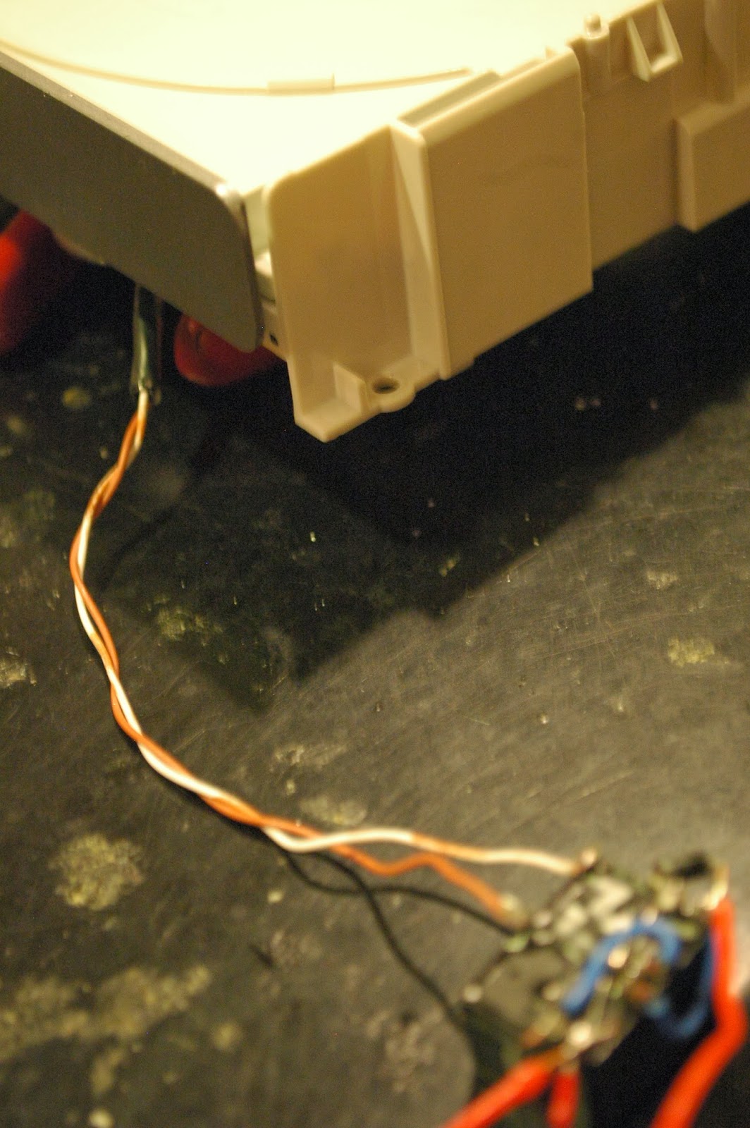

 If you can follow the schematic you are golden. Make a PCB, use a perfboard, whatever; I just made a rat's nest to keep it small.

Here is a video:


It is a bit kicky, probably because of a current issue, but it works for now.
And it's a lot cheaper than the other PCB agitators, using less parts :D

I hope you enjoy it.

Saturday, October 12, 2013

WIRELESS 555 timer mouse modification

It's Columbus Day weekend and I had an urge to do this project ever since I got back from Hong Kong, so I decided to do it this weekend.

You might be familiar with this "mod" on gaming communities, whether it be for Xbox games or for computer games. Basically you add a 555 timer sends an oscillated signal to a button to simulate extremely fast clicking.

This is my old mouse

I did this to my old mouse and I used it a lot for my games.

I found an awesome wireless mouse in Hong Kong that only costed $5, and I loved using it. It was more sensitive, and, wireless! My desk was beginning to get cluttered so I was more interested into going wireless.
The bad thing is, it doesn't have this rapid-fire button on it.

The 555 timer runs at 5v. If I tried to put that circuit into a mouse running at 1.5v, I would have a bad time.
I dug the internet for solutions to this problem, and found nothing. I have yet to find a web page that has instructions on how to build a rapid fire circuit for a wireless mouse, or even proof that it has been done.
The only thing I found was this. Sad.

Apparently, TI sells and low voltage variation of the 555 timer, the LMC555. It's CMOS, so it runs with less power.
TI claims that it has this swap-out property, so I can just replace a normal LM555 with a LMC555 and everything will still work. I had to see this for myself.

So I ordered a few and built the circuit as I always would. Here is a schematic

I will explain the transistor later.


So the first step is to take apart the mouse.
Good job!

Now, build the circuit on a breadboard so that you are sure everything works.


Test it


You should get this really quick square wave.

Now you are going to have to do a little testing (with a multimeter)on the mouse now.
Most wired mice have a button that when you click it, it shorts HIGH to the processor. When the processor picks up the HIGH, it takes it as a click.
This wireless mouse does something else. When the processor senses that a pin is LOW, it considers it a click.
From the two button pins, find the pin to the processor (2-3v) and the pin that is LOW (0v).


Test each lead of the button.
To find out whether your mouse is activated by HIGH or LOW, click the button and see if both pins are HIGH or LOW.
If both pins end up HIGH (3v), you don't need a transistor.
If both pins end up LOW, you need a transistor.
When the transistor receives a signal from the base, current will flow from collector to emitter. Emitter will be connected to ground, and the collector will be connected to the processor pin (2-3v).

Try using a wire to short your processor pin to GND. See if that renders as a click.

So now that you cleared that up, solder the circuit together! Remember to make it AS SMALL AS POSSIBLE. Space is an issue. You have a battery, a button, and your 555 circuit all crammed into the already tight space in the wireless mouse.

bend the leads


Solder tightly


After that, drill your hole for you mouse. You must find a button that fits your mouse.

Just adding the transistor


Find the right drill bit


Seems to fit


It fits!

So now that is done,
Connect the 555 timer to Vcc and GND
Connect the emitter of the NPN transistor to ground
Connect the collector of the NPN transistor to the processor pin (or the button pin that has 3 volts)
Connect one end of the button the the base of the transistor
Connect the other end of the button to the pin 3 of the 555 timer.

Some pictures of that:


Wrap it in electrical tape for insulation


fits nicely


And you are set!

Here is a video of it working. Note that this mod is pretty glitchy, and sometime it will not respond, but it works most of the time.


Friday, August 30, 2013

Boredom and fun

Project #1, LED flasher!

Hello world,

This is my first blog post on this blog, so I think I shall start with something simple.

The 555 timer: What it generally does is this:


The output is from pin three. Hopefully this picture will show you how it is wired:

A little background: I learned about electricity in 6th grade at school. I was incredibly intrigued by LEDs and switches. This was my first project for the 6th grade science fair:

Sadly I had to get rid of it, so this is all I have.
Basically, there is a car that is solar powered. The car is dragging a piece of wire.
What does that wire do?
If you look at the track, you will notice that I have tin foil on the surface. The inner side of the tin foil is grounded, while the outside tin foils are connected to the cathodes  of many LEDs connected in parallel.


When the car passes an LED, it will connect the cathode of the LED to ground, and that LED will light up.
As the car passes that LED, it will turn off, and turn the other one on in succession.


So, my first official projects with electronics started in 8th grade. It was February, I had a fever from my allergies, and I was bored and stuck at home. My brother recently came home from college with a bunch of gifts: 555 timers, 741 op-amps, logic chips, lasers, etc.

So, I googled what a 555 timer was. I found a cool project, and did it.
A 555 time bomb.
It was fun. Then, I made a blinking LED, then a fading LED, then a 555 piano... 
I had to get rid of those too, so, sorry, no photos.
However I do have a recording of a simple 12v led flasher, when I learned about the Esaki effect:


Then I had to try this popular mouse modification: rapid fire.


It's really useful when playing CS:GO.

Then I moved on to 741 circuits, such as an audio amplifier, a heat activated fan (show in later blog), and some other failures.
Then I did some LM386 audio amplifiers (show in later blog), and some TDA amplifiers.

While all these projects were being completed, please note that I used these skills to help me repair broken speakers, broken electronics, etc.

So what's the point?

Last week I was at Cornell, with my family, helping my sister move into her dorm.
They were giving out free things that day: an LED flasher, for example.
I got bored, so I took it apart. Look how much fun this is:

This is the start of this blog, so I hope you find some projects that you like!
You can comment if you have any questions.