Showing posts with label Soldering Iron. Show all posts

Sunday, November 10, 2013

VU meters evolution

A few years ago I designed an awesome circuit.

Awesome:

My definition of awesome:
  • cheap
  • easy
  • practical
  • awesome
I was searching for a way to build a VU meter. Before microcontrollers, all my projects were audio based: I just wanted to find ways to make my desk/room/life awesome. I built amplifiers, blinking lights, speakers, etc. I wanted to build a VU meter, so I fould the LM3916/3915/3914 family.

LM3916

I heard/read that this chip works logarithmically. That means that each LED that lights up is one decibel.
Of course, like all the other chips in this family, it runs on 6v or higher and has the option of dot display (one dot) or bar display (bar VU).

LM3915/3914

I think these two are almost the same. This chip works linear, so it isn't great for measuring decibels, which is logarithmic. It runs on 6v or higher, and has the dot display or bar display option.

So anyways, I built a few of these VU meters, the first ones being failures.

I don't even have pictures of it: It was my first attempt at double sided PCB and I failed pretty badly. It was operated by a microphone, ran on 9v, and had an LM386 as an amplifier.


In those days, I learned that the less components you use, the better the circuit works (I was guessing and checking). For example, I built an LM386 amp that week and I took away a bunch of capacitors and resistors and the end product was amazingly better than the original schematic.

So, I used that philosophy to build this. I ended up with a USB powered VU meter with only a chip and 10 LEDs as necessary parts. Everything else is optional.

The Chase

Let's cut to it.
Here is a video of my 3rd VU Meter. My second one is the same, but with a wire instead of a plug.

The audio is gone: it was Hotel California...

That's the third one. I decided to make a new one, one with a more flexible profile, so let me show you how I made it...


FIRST
Choose your chip...
and buy THESE LEDs. I'm not sure if other LED's will work: these LEDs work well at low voltages.

I found these on ebay for pretty cheap. $5 for 100!

Next, just look at all these pictures...

Design


Print design onto transparency


Ready the developer, Plexi-glass, and PCB


Arrange design onto PCB, place plexi-glass on to, and light it up.


Meanwhile get the materials


  • LM3916/3914/3915
  • Resistor (or jumper, depends on if you like loud music or not)
  • Audio plugs
  • 5 SMD LEDs


8 Minutes, 


place in developer


let it set out


Looks about right


Clean it up if needed


Start etching


Clean with acetone


Drill holes


Steady the board. Get your tweezers and your SMD LEDs. Add a blob of solder on one end of each SMD LED pad.


Solder one side of it


Reheat the joint and slide in the LED


Finish soldering the other edge


Looks like I forgot to drill some holes
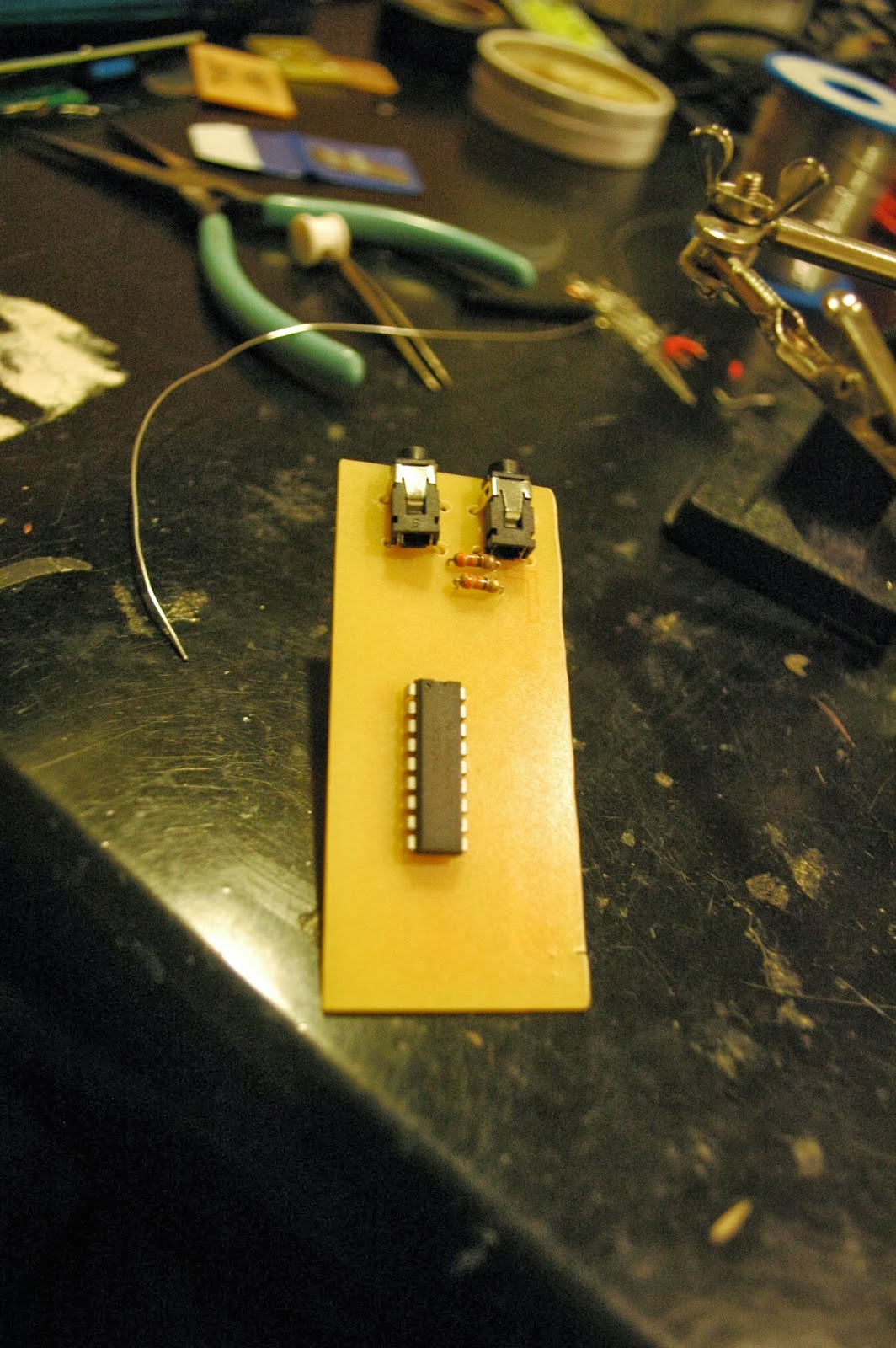

Add top components and finish


Wow


much cool


Once you test that it works,


Clean it and 


Cover in nail polish.


wow.

Saturday, August 31, 2013

Let's get familiar with some tools

Before all of these posts...

Let's get familiar of all the tools I will be referencing and using. This is going to be a quick run through, so if you have any questions of where to purchase, how to use, etc about the tools, please leave it in the comments below.

Taken for granted:

I hope you all know what a breadboard is, what solder is, what a perfboard is, what a PCB is, etc.
If you have any questions about electronics, please feel free to ask questions!
I will not mention every single tool I use, as I am skimming through it.

Tools

Soldering iron: ~$10
Less basic and less useful: solder pot. ~$15
I barely ever use the solder pot. In fact it isn't even that practical.
The only thing I use it for is to desolder SMD parts, however I could use a hot plate instead of it. It makes a lot of harmful fumes, and the solder oxidizes quickly in such a hot pot. 


Etchant ~$3
I bought etchant from Hong Kong, cheap. 
Dremel ~$expensive (my dad's)
Drill press base ~ $founditinthetrash
Hacksaw ~$I'mnotsure
Goggles ~$finditinthetrash
gloves ~$inthetrash
Vise~$mydads

Here is a picture of the table which I work at. It is incredibly sloppy at the moment. However, you will see that I have wire strippers, wire cutters, pliers, helping hand, etc.

Helping Hands ~$20 (from Hobby Shop. If from Radio Shack, it probably costs a ridiculous price)


Organized box of supplies:
This year I went to Hong Kong and bought parts like no tomorrow. Why?
Two seven segment displays in HK cost $8... HKD, which is one US dollar
That same product probably costs $4 in USD... At Radio Shack.
I prefer to order parts from ebay.com. The shipping takes long, but if you do not need the part urgently, you will be satisfied.


Brilliant.


Multimeter: useful, and relatively cheap in HK. Fluke multimeters are a recommended brand... because they don't fluke (haha)

Just a handy notepad to write down reference circuits or pinouts that you will need to use a lot.


A laptop comes in handy to program and surf the web for help!


A USB to Serial converter will be handy. This one is from ebay, again, pretty cheap ~$10
I tried to make my own, but ended up failing.


Home-made tools

The tools above can be bought. The tools I will soon mention can be made at home, for a much cheaper price.

Inside this box is magic. Let's open it.

Test LEDs. Having a built in resistor comes in handy. To test if a connection is HIGH (5v) or LOW (0v), just connect this resistor like a pair of chopsticks. It's a good tool, simple to make.


Above is an "oscilloscope", more like a graphed out voltmeter that I found here: http://yveslebrac.blogspot.com/2008/10/cheapest-dual-trace-scope-in-galaxy.html
It's functional, but a better option would have just been
analogRead(); on Arduino, then graph it out on processing.


USBTiny ISP. From Adafruit, this tool is somewhat expensive: http://learn.adafruit.com/usbtinyisp
From ebay, it is a little less expensive: ebay.com
From home, it's free.


This brilliant piece of work can be found at this guy's blog: http://tequals0.wordpress.com/2011/09/26/attiny45-based-usbtinyisp-programmer/

If you check the comments you might be able to find the PCB I designed. 

And with all those ISPs, how do we program with them?


Voila! Most people put their chip on a breadboard every time they need to program it...
That can be a bit annoying, so I made this target board. It supports 
  • ATtiny25,45,85
  • ATtiny24,44,84
  • ATtiny1313,2313,
  • ATmega 328,128, similar chips
Basically you plug in the ISP cable, the chip, and if you need, there is a socket for a crystal oscillator, and you can program it! All it is is a connection between the ISP header and the MOSI, MISO, SCK, Vcc, GND, and RST pins of each chip socket, so of course, you can only program one chip at a time.

5v power supply: four sockets from the USB so it's easy to prototype


An audio jack with wires sticking out of it. That way I can just plug the wires into a breadboard to test out an audio circuit.


This board is to be used with the Arduino as ISP system. you can find it here:
My board supports only ATtiny25,45,85 and 24,44,84, so I do not use it often.


Last but not least, above are pictures of a debricker I found online. 
The best thing, It WORKS and it's small.
 I used an A23 battery cell for size. It's impressive such a small battery is 12v!
From the hv_serial_prog program on that website, I edited a bit so I can reset the fuses on different chips. All you have to do is change the values on the #define at the beginning.

So, feel free to make your own! I encourage you to make these tools so that your life will be easier.