Saturday, August 31, 2013

Raspberry Pi Review

Okay, its cool. I admit.

However, I have some opinions about it that might help you before you go ahead and buy one.

Why did I buy one?

My friend bought two because there was free shipping if you did so. So, I took one off of his hands. Good deal; I didn't have to pay shipping.

Pros:

  • $35
  • GPIO pins
  • uses Python; good for educating about programming
  • Easily implementable into permanent projects like arcades.

Cons:

  • $35!
  • Only two USB ports? It can't even power a regular USB stick
  • No VGA?
  • How do I plug in an LED into this GPIO pin...
  • No keyboard
  • How do I find an affordable HDMI monitor?

Okay, maybe I am complaining too much.
But what is this?

Laptops for about $40. Keyboard, USB, monitor, mouse, all included.
Maybe it doesn't have a GPIO pins, but it probably can program an Arduino
Debian can be easily installed on this computer.

This is the current setup of the Pi:


I'm using the analog video output to the monitor.


I decided that I wasn't going to buy female wires, so I just made this adapter.


In the end it's a good board for hobbyists to use, but for all the functions that it claims to have, there is always a better alternative.

I wouldn't say it's a terrible board, but I wouldn't go tell someone to buy it. There are alternatives.


DIY Arduino Duemilanove

Or the DIYmilanove


lol.

Back in the day when I was starting to learn about Arduino, I decided that the best way to learn how it works was to build it myself.

I wanted to make an Arduino that was exactly like the real one. That means:

  • Same footprint
  • I can fit shields onto it
  • I can program it from the USB port
  • There is serial communication
  • I have an ICSP if I need it
  • There is an LED on pin 13
  • a reset button
Basically, it must function like a real arduino.

It took a week to complete this board. A lot of research went into it.
In order to make a board like this, you must look at the original schematic, look at your own needs, look at the parts you have, and try to build something similar to the real thing with the parts you are limited to.


Please read through it if you plan to make your own Arduino. For example, I did not know that the ATmega 328 was not the same as the ATmega328P.

So, here are some pictures of the process:

I used an Arduino shield to make sure I was putting the headers in the right place


Adding some wires and buttons... some capacitors


Board is almost complete. Needs to install a 3.3v regulator, the chip, and the Serial converter.


Board finished


sloppy underside


the chip!


Yea... I gave up in soldering an FTDI chip, so I just bought one.


FTDI converter


More pictures


the belly.


In the end, all you need is the schematic of the Arduino. Then, you gotta place the parts in the right places. After that, just solder wires until the whole thing is wired up and it is ready to go!


DIY Arduino Mega 2560

Alright.
Here's the story: I was working on this frustrating Arduino project, and I decided to take a break. I went away to watch a little Star Trek and drink some water.
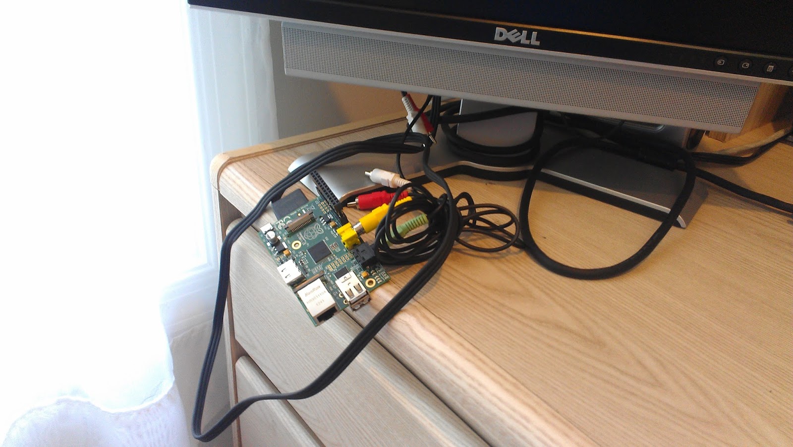
When I came back, my Arduino Mega was hot: really hot.
In this area:
The Arduino was not responding to the IDE. The only way I could program it was by using the USBtiny ISP.
That pretty much ruins the purpose of an arduino board, so I brought out the solder pot, desoldered the whole board, salvaging as many parts as I could.
Since the ATmega 2560 was not damaged, I decided to put it back to use:
The following is the process of how to

Make your own Arduino Mega

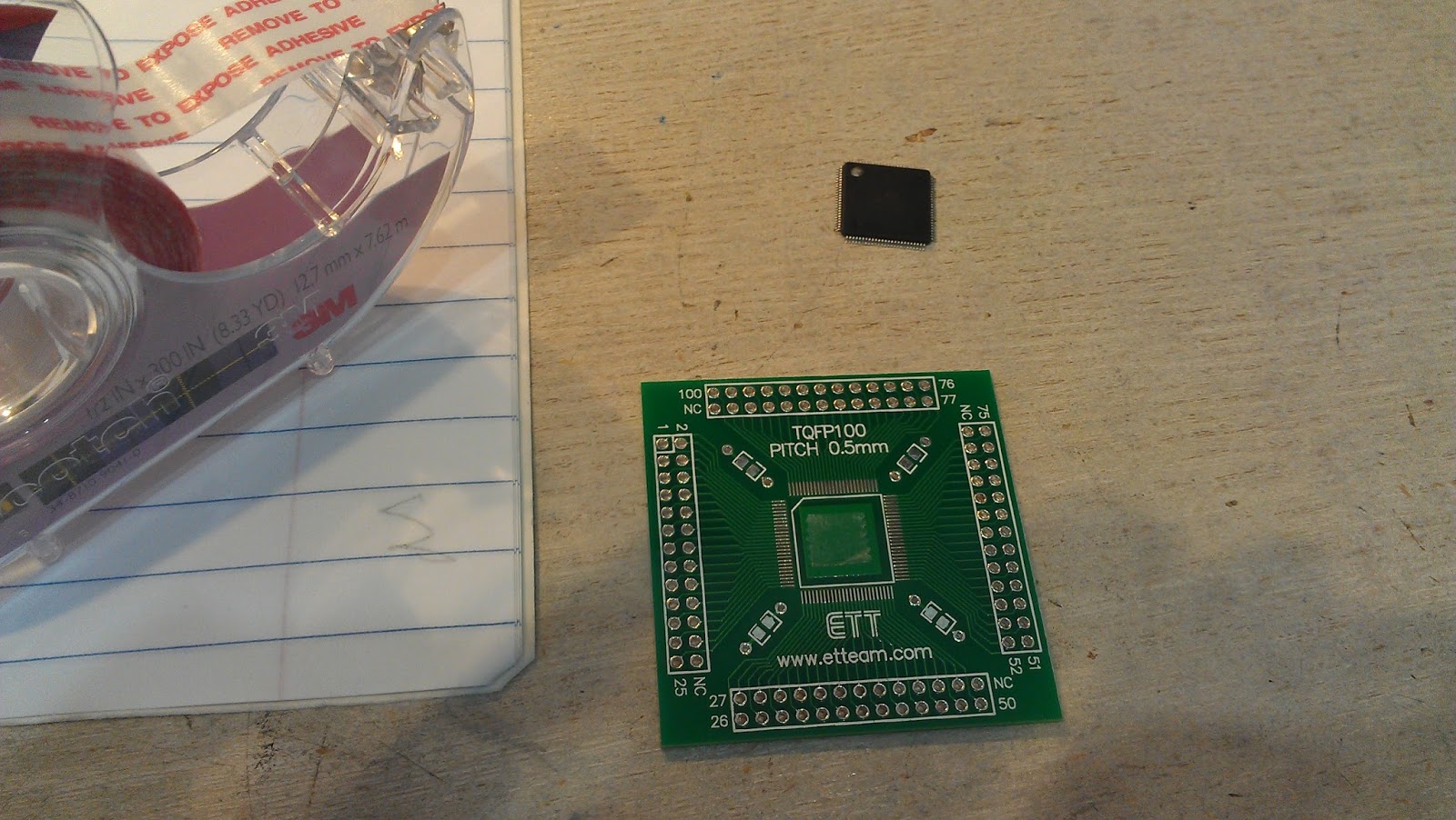
You think it's hard to solder SMD? Think again. This was my first time soldering SMD chips with 0.5mm pitch (in other words, REALLY SMALL).

Parts needed:

  • TQFP100, 0.5mm pitch to DIP adapter
  • Momentary push button
  • 6 headers (for ISP)
  • lots of wires
  • flux
  • Perf board
  • 16 MHZ crystal (if you salvaged chip from Arduino Mega)
  • OPTIONAL but recommended - double sided tape
  • OPTIONAL - 330 - 470 ohm resistors *2
  • OPTIONAL - two LEDS
  • OPTIONAL - 5 more headers for FTDI Serial communication
  • OPTIONAL - nuts and bolts

Step One

Stick one or two pieces of square double sided tape on the breakout board. This might help keep the chip in place when soldering it.

Step Two

Place the chip on! Please note the index corner on the chip to align it correctly. Make sure that the leads on the chip and the board line up REALLY well. The must be aligned.


Step Three

Time to start the soldering: apply WAY TOO MUCH flux (that means A LOT) onto the edges of the chip. You will need to use all of it, and maybe some more.
The secure the board:

Step Four

I do not have pictures for this. You will want to put a nice drop of solder on your iron and just drag it across the edges of the chip. Don't worry, it's all being soldered, even if you do not think it is.
You will probably have many solder bridges (especially on a chip this small).
Thats OK, just gently drag it off with the iron tip, use a solder sucker (be careful with it, you might bend the leads), or use even more flux to remove it. This step might be the most difficult

Step Five

Clean off the flux with water or alcohol:

Test the connections: any shorts? Something not connected?
Then you may proceed to cut and solder in some headers.


Then maybe you want to drill some holes in the four corners, if you want to.

Step Six

This step is mildly annoying. Print out the datasheet of the 2560 and start marking where
MOSI
MISO
SCK
TXD0
RXD0
pin#27
VCC
GND

or any pins important to you, are
Mark it all!

This might help:


Step Seven

Start preparing your perf board. This step is very subjective to your needs and tastes. I like to have the TX and RX header so I can program this like a regular arduino.
I like to have a reset button
I like to have an LED on pin D13/ 27 of the chip
After all, it is a development board.


Start wiring the board!


Do some three dimensional wiring now.


Step Eight: last step

Time to test it....

The ISP programming worked!

Serial communication works.


 FINISHED:


Static......

Alright. It worked. Beautifully.
But I have something to admit. As I am typing this post, The finished board is hung up on my wall as a failure.

Why?

I can't use it as a regular Arduino Mega as I wished. Well, maybe I could have, but you will see why I couldn't.
The old Arduino Mega uses the FTDI UART, however the chip was the ATmega1280
I have a 2560, so I would need to go into some hassle to add a new board bootloader into Arduino IDE and all that trouble is just not worth it.

It definitely can be accomplished, however before I could do anything, the board burnt out.
*sigh*
I was in the middle of testing the serial communication: it worked perfectly. After five minutes, however, it started glitching. Then there were sparks... then smoke, then everything went south.
What happened?

/********************************************************************************/
READ THIS
When soldering in the oscillator crystal, make sure it DOES NOT SHORT THE LEADS. Note that it has a metal casing, so it should either be masked with electrical tape or place in another area.
Don't do this:
That ended up shorting XTAL 1 and 2, Vcc, and GND all together. The chip smoked and I wasted a lot of effort.

Lesson learned! *thats another nugget of information buddum crash*

As long as you follow all of these instructions, however, you will be able to accomplish what I would have if I have not made that mistake!


Arduino? or not Arduino...

Alright, Some of you might know about Arduino, some of you might not.

All it is is a microcontroller on a board with sockets so it makes your life easier: nothing fancy.
They have a voltage regulator, a built in programmer, and all the nice peripherals in one board to make it a beautiful prototyping tool.
The IDE is easy to use too!

Well, I'm not going to explain what Arduino is on this blog. You can find that on Arduino.cc.

I'm going to talk about authenticity.

Recently I bought an Arduino Mega 2560 R3 on ebay, from China. Why?

  • It costs $15
  • I burnt out my Revision 2 board
  • I don't really care about authenticity of an Arduino
It shouldn't really matter whether an Arduino is supplied by Arduino or not. In fact, Arduino open sources their boards, so anyone can make an exact replica of the real Arduino boards.
If its fake, it will still work; because it's an exact copy.

How do I tell if it's fake?

This is fake
This is real

Notice the different LED colors.

This is fake
"ROARD"

This is real

"BOARD"
How did THAT happen?


This is fake


This is real


Notice that the fake Arduino has shiny solder, which means it contains lead, which means it is not RoHS, which means that it is probably not authentic.

Lastly, A single component comparison:

You might notice some color differences.

It's not that important, but if you want to sue someone, here is the evidence.


Let's get familiar with some tools

Before all of these posts...

Let's get familiar of all the tools I will be referencing and using. This is going to be a quick run through, so if you have any questions of where to purchase, how to use, etc about the tools, please leave it in the comments below.

Taken for granted:

I hope you all know what a breadboard is, what solder is, what a perfboard is, what a PCB is, etc.
If you have any questions about electronics, please feel free to ask questions!
I will not mention every single tool I use, as I am skimming through it.

Tools

Soldering iron: ~$10
Less basic and less useful: solder pot. ~$15
I barely ever use the solder pot. In fact it isn't even that practical.
The only thing I use it for is to desolder SMD parts, however I could use a hot plate instead of it. It makes a lot of harmful fumes, and the solder oxidizes quickly in such a hot pot. 


Etchant ~$3
I bought etchant from Hong Kong, cheap. 
Dremel ~$expensive (my dad's)
Drill press base ~ $founditinthetrash
Hacksaw ~$I'mnotsure
Goggles ~$finditinthetrash
gloves ~$inthetrash
Vise~$mydads

Here is a picture of the table which I work at. It is incredibly sloppy at the moment. However, you will see that I have wire strippers, wire cutters, pliers, helping hand, etc.

Helping Hands ~$20 (from Hobby Shop. If from Radio Shack, it probably costs a ridiculous price)


Organized box of supplies:
This year I went to Hong Kong and bought parts like no tomorrow. Why?
Two seven segment displays in HK cost $8... HKD, which is one US dollar
That same product probably costs $4 in USD... At Radio Shack.
I prefer to order parts from ebay.com. The shipping takes long, but if you do not need the part urgently, you will be satisfied.


Brilliant.


Multimeter: useful, and relatively cheap in HK. Fluke multimeters are a recommended brand... because they don't fluke (haha)

Just a handy notepad to write down reference circuits or pinouts that you will need to use a lot.


A laptop comes in handy to program and surf the web for help!


A USB to Serial converter will be handy. This one is from ebay, again, pretty cheap ~$10
I tried to make my own, but ended up failing.


Home-made tools

The tools above can be bought. The tools I will soon mention can be made at home, for a much cheaper price.

Inside this box is magic. Let's open it.

Test LEDs. Having a built in resistor comes in handy. To test if a connection is HIGH (5v) or LOW (0v), just connect this resistor like a pair of chopsticks. It's a good tool, simple to make.


Above is an "oscilloscope", more like a graphed out voltmeter that I found here: http://yveslebrac.blogspot.com/2008/10/cheapest-dual-trace-scope-in-galaxy.html
It's functional, but a better option would have just been
analogRead(); on Arduino, then graph it out on processing.


USBTiny ISP. From Adafruit, this tool is somewhat expensive: http://learn.adafruit.com/usbtinyisp
From ebay, it is a little less expensive: ebay.com
From home, it's free.


This brilliant piece of work can be found at this guy's blog: http://tequals0.wordpress.com/2011/09/26/attiny45-based-usbtinyisp-programmer/

If you check the comments you might be able to find the PCB I designed. 

And with all those ISPs, how do we program with them?


Voila! Most people put their chip on a breadboard every time they need to program it...
That can be a bit annoying, so I made this target board. It supports 
  • ATtiny25,45,85
  • ATtiny24,44,84
  • ATtiny1313,2313,
  • ATmega 328,128, similar chips
Basically you plug in the ISP cable, the chip, and if you need, there is a socket for a crystal oscillator, and you can program it! All it is is a connection between the ISP header and the MOSI, MISO, SCK, Vcc, GND, and RST pins of each chip socket, so of course, you can only program one chip at a time.

5v power supply: four sockets from the USB so it's easy to prototype


An audio jack with wires sticking out of it. That way I can just plug the wires into a breadboard to test out an audio circuit.


This board is to be used with the Arduino as ISP system. you can find it here:
My board supports only ATtiny25,45,85 and 24,44,84, so I do not use it often.


Last but not least, above are pictures of a debricker I found online. 
The best thing, It WORKS and it's small.
 I used an A23 battery cell for size. It's impressive such a small battery is 12v!
From the hv_serial_prog program on that website, I edited a bit so I can reset the fuses on different chips. All you have to do is change the values on the #define at the beginning.

So, feel free to make your own! I encourage you to make these tools so that your life will be easier.