In honor of my recent watch obsession and in obligation to post an old project, today I'll talk about my DIY Apple Clock.
Ever since I started tinkering with electronics I always wanted to build a clock of some sort. I feel like that's a sort of rite of passage for a lot of tinkerers.
Building a clock tests your ability of learning how to use seven segment displays
It also tests your understanding of keeping in your program and how to handle interrupts
For me, I finally decided to build a clock because I wanted to build something beautiful and elegant. Most of the time I leave my projects as bare circuit boards... because I think it already looks nice. This time I decided to at least have an enclosure.
I also had these bubble displays lying around, and I thought they looked pretty damn nice.
I also just came back from a summer program and got over my fear of reading datasheets. I took the opportunity of summer to test my datasheet reading abilities and use something outside of the comfort range of Arduino.
The full Instructable is in that first link: I'm only going to give a digest of the project.

1x PCB (not shown)
1x Apple earbuds case (not shown)
1x 74HC595 shift register
1x ATTiny44 or ATTiny84
1x 16MHz crystal oscillator
1x 1N4001 or 4007 power diode
1x USB B mini port
1x Li-Ion rechargeable battery
1x bubble display
These two bags of nuts and bolts I bought at RadioShack and I don't know what to call it but its in the pictures
2x pushbutton switches
3x 10 kohm resistors
4x 330 ohm resistors

I explain in heavy detail in the Instructables how I used Pin Change Interrupts (PCINT) instead of External Interrupts (INT)
Here are good reads:


That was the DIY Apple Clock.
I should be up to speed now with all of the projects that I posted on I'ble but not on here. It's time to think of something new...
Ever since I started tinkering with electronics I always wanted to build a clock of some sort. I feel like that's a sort of rite of passage for a lot of tinkerers.
Building a clock tests your ability of learning how to use seven segment displays
It also tests your understanding of keeping in your program and how to handle interrupts
For me, I finally decided to build a clock because I wanted to build something beautiful and elegant. Most of the time I leave my projects as bare circuit boards... because I think it already looks nice. This time I decided to at least have an enclosure.
I also had these bubble displays lying around, and I thought they looked pretty damn nice.
I also just came back from a summer program and got over my fear of reading datasheets. I took the opportunity of summer to test my datasheet reading abilities and use something outside of the comfort range of Arduino.
The full Instructable is in that first link: I'm only going to give a digest of the project.

This is a picture to show you how the completed product looks. More photos at the end.

Here is a layout of the parts we need.

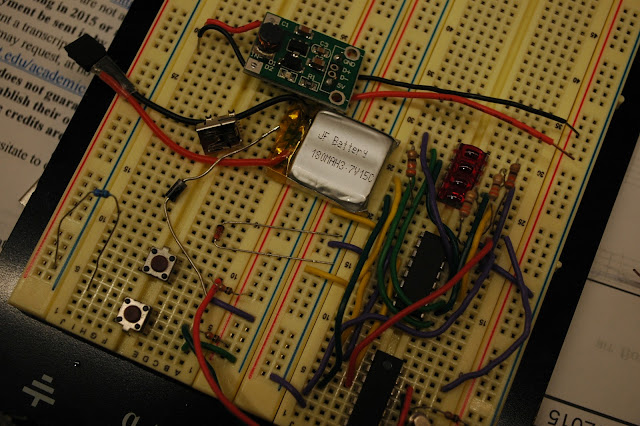
This is how the working circuit looked like on a breadboard. Most people who build clocks go ahead and use the ATMega328... I wanted to challenge myself and make the design as cost effective as possible, so I used the ATTiny44. It was fun reading the datasheets to get the most out of the chip.
Here are good reads:
- http://thewanderingengineer.com/2014/08/11/arduino-pin-change-interrupts/
- http://thewanderingengineer.com/2014/08/11/pin-change-interrupts-on-attiny85/


Also featured in this project is multiplexing. How did I control 28 segments with only 3 pins???

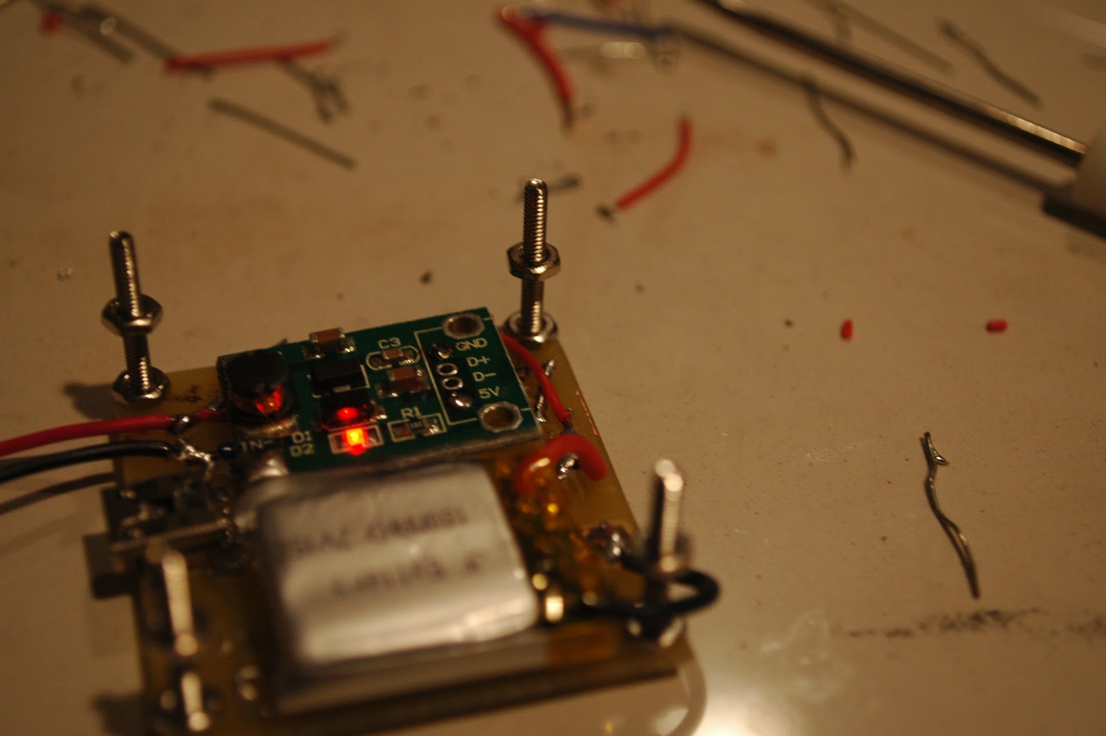
This is just another shot of the circuit. That green circuit board that has the light on is a voltage step-up. You can see the whole circuit being powered from one AA battery.

After the circuit was verified, I designed a PCB

This is a second layer of the PCB for the power circuitry (charging and regulating)


Printing out transparencies and cutting out fiberglass board.


Exposing the board for 7.5 minutes.


After putting the board through developer, this is how it turned out :D

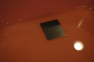
Throw it into some etchant.
I don't recall if I ever mentioned what etchant I use... This is a mixture of HCl and H2O2

Expose and develop the second board!


Ayy


After a really long process of waiting, this is how the boards turned out.

Drilling the holes.

Upload the code.

Featuring: ATTiny44 and the $5 USBTiny programmer

Sadly RadioShack is going out of business... I bought these nuts and bolts out of pity.


This is how the finished power supply board looks like. the Li-ion battery is glued onto the board, and the leads soldered to the board. I also soldered the green board directly on. A USB port is added to allow charging.

Finished main circuit board. The button on the left decreases time, the right increases.

Adding the screws onto the power board.

Soldering the power wires to the main board.

It's alive!


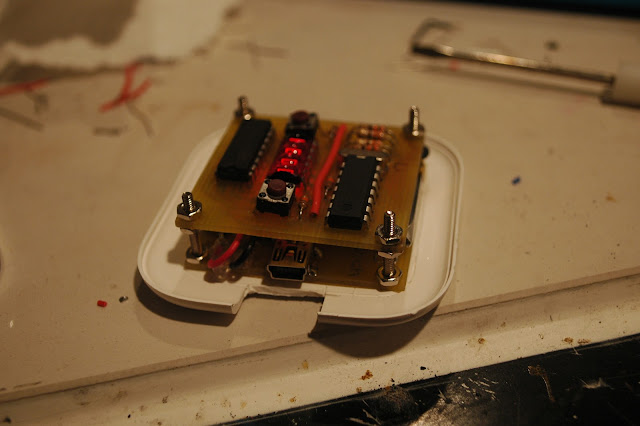
After it's wired, I mounted the main board on top of the power board.


It looks like a beautifully made sandwich.

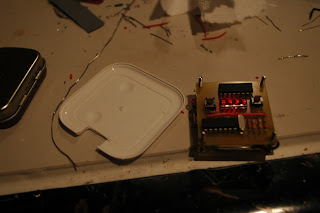
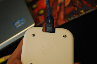
The next objective is to fit this device into an Apple Earbuds case.


I had to cut this groove for charging.


Drill 4 holes for the screws.


Everything mounted on


I had to cut the screws down in size using a diamond cutting bit. I covered the circuit with masking tape so metal dust wouldn't fly into the circuit and short everything out.


Two holes were drilled so that you can change the time by pushing the buttons.


And it's finished.


I should be up to speed now with all of the projects that I posted on I'ble but not on here. It's time to think of something new...