Feel the power of making a professional-looking circuit board at home with these amazing chemicals that eat copper.
Pretty rad.
Sadly, not everyone can get their hands on etchant, or photosensitive boards, or any of that fancy stuff. As always, I investigated a cheaper way to make PCBs. I'm not talking about that 3D printing stuff or the conductive ink pens (those things are not cheap to begin with).
I'm talking real lyfe.
Okay. So the objective of this was to make a PCB that could use any substrate. That means I could implement a circuit on any surface: wood, glass, plastic, curved surfaces, paper, maybe even clothing!
Before we continue on how I did this, we must first understand how PCBs work.
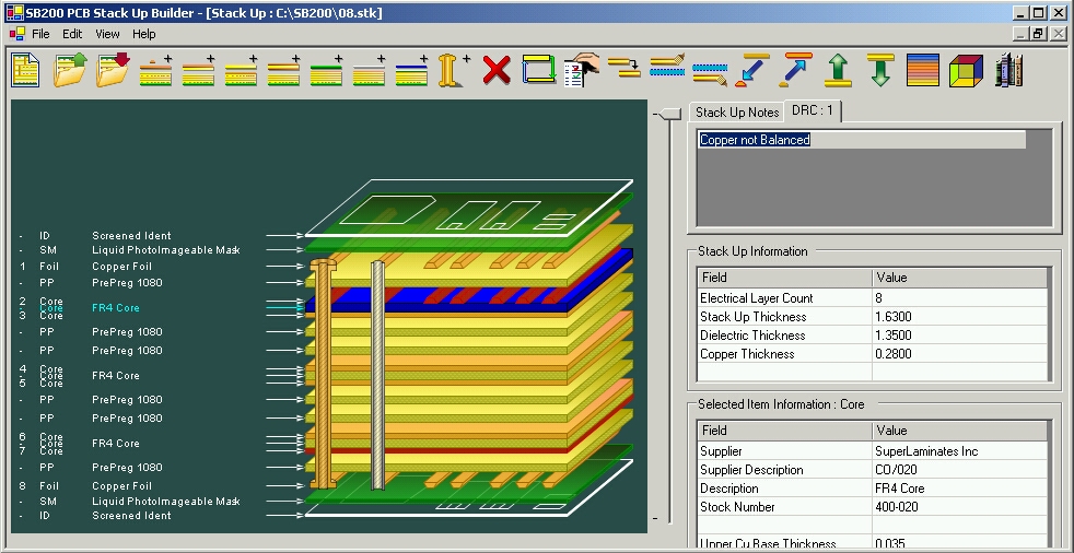
Basically, a sheet of copper is pasted on top of an insulative substrate: usually phenolic or fiberglass, or flexible plastic. Printed Circuit Boards are much more sophisticated today, with multiple layers. These layers are connected through vias. Like elevators, they are conductive holes that transport electrons.
Here are some pictures from the internet:
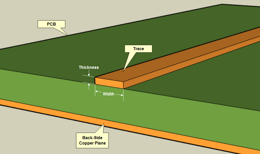
As you can see, each trace is like a wire, a road to move electrons.

PCBs can get crazy, with layers of different types of conductors. A solder mask is that green thing that prevents the PCB from oxidation or shorts.
More.
You could look at my post on VU meters evolution to get an idea of how I do it at home.
So, it seems like PCB manufacturing at home is limited to copper boards on phenolic/fiberglass surfaces.
Instead of using copper sheets (because they were not cheap), I used aluminum foil as the conductor. Instead of using fiberglass/phenolic, I used whatever I felt like. The following is my attempt on aluminum PCBs.

I decided for attempt 1 that I was going to use a plastic sheet

For this first attempt I was going to use SMD parts, so I do not have to drill holes (the DIP parts will be bent into SMD).

Sanded out

Just programming the chip


I really had no photosensitive aluminum foil, so I would use the toner transfer method.

I cut out one piece.

Taped it to aluminum foil. The back of the foil has a piece of tape to keep it flat.


Then I ironed it. The tape melted, which was bad...

The toner stayed intact with the foil, but the end product wasn't flat.

Use crazy-glue to glue it onto the plastic

Bath in water to remove the paper

It did not glue on too well... there were air gaps and wrinkles

dangerous chemicals.

crack a window.

two parts hydrogen peroxide


one part hydrochloric acid

It should etch the aluminum pretty well.


You will start to notice that the etchant gets in the cracks...

It etched away at traces from below.


So this time, I would glue the aluminum onto a flat surface first.


Then I drew silly patterns on it with a circuit-writer pen (an oil based ink pen, it's a Sharpie in essence).


I put it in.

Working well!

Then the ink started dissolving...


It didn't come out too well...
You must always put the substrate on the foil first to ensure an airtight bond that will not allow any etchant in between.
This means that you cannot use a substrate that melts under a clothing iron, because...
Conclusion from attempt 2:
Oil based ink does not last too well in our etchant.
This PCB attempt could have been successful, if I were using glass, for example.
However, I was not using glass. In the end, this was pretty much a failure. The goal was to use any substrate. I am currently limited to substrates that do not melt under a clothing iron.
This gives me a nugget of information for my next attempt though, which is good, so I got that going for me.
About Metal Core PCB: There is a good deal of advantages connected to aluminum based PCBs since aluminum is secure and last lasting.
ReplyDelete